RL-01 Installation in F355
Installing the RL-01 Reverse Gear Lever Repair Kit in a Ferrari F355
Contribution by FerrariChat member FCOnyx
Parts:
You *may* also need a new 3mm x 40mm screw, but wait until you've got your unit apart to purchase one. We'll explain below.
Tools:
- Small Philips screwdriver
- Medium Philips screwdriver
- Small flat-head screwdriver
You *may* need a razor blade cutting tool, small file, large file, vice and a Dremel with a cutting wheel. Again, wait until you have your unit apart. Explanation below.
- Start by removing the F1 control box from the console via the 4 large Philips screws. Take care not to slip the screwdriver!
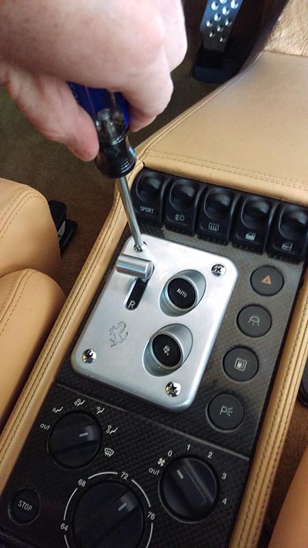
- Remove the F1 control box from the console by pulling the front up and then forward so that the connector cable can clear at the rear.
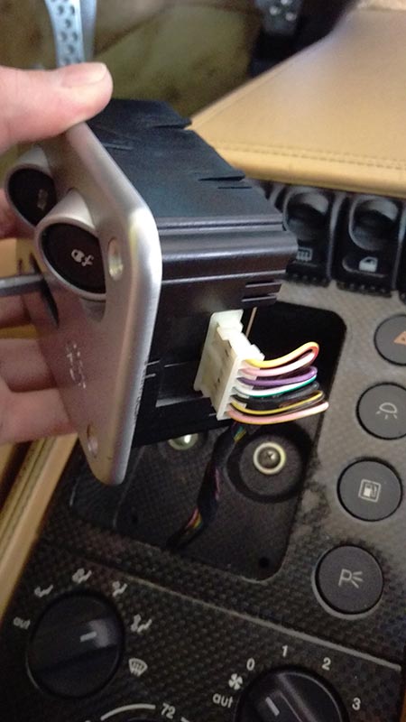
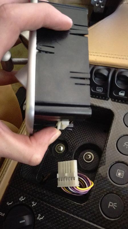
- Disconnect the connector cable. This is done by pulling up on the tab at the center top of the white connector and then sliding the connector out
- Once the F1 box is out and disconnected, flip it over and remove the black cover from the bottom of the unit. This is done by gently pulling the small locking tabs on each side. It may be easiest to start with the two tabs on the end where the cable connection resides, then working my way around.
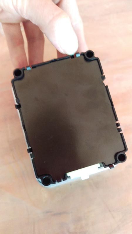
- This is where you may need a razor blade cutting tool and small file. Some owners have a screw in the center of the green PCB, while others do not. Ignore the 3 black screws near the edges, the only one that is important is the one in the center. If you do not see it, then you'll need to cut a hole in the center of the PCB to get the screw underneath. Start by razor cutting the small hole in the center of the PCB just beneath the "y" in the word Germany. Work it with the blade and then small rounded file until it's large enough to get a screwdriver to the screw beneath.
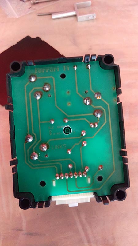
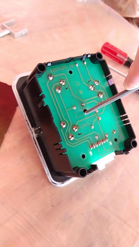
- Unscrew the center screw. The silver portion will now separate from the black portion. Be careful of the small springs that hold the old Fork in place. They are moderately secure, but can pop out, so be diligent.
- Once the silver portion is off you'll see the old fork. The small flat-head screw in the center is what needs to be removed next. (You'll also probably see pegs broken off the old fork and/or the small plastic grommets that wrap the pegs being broken/shredded.)
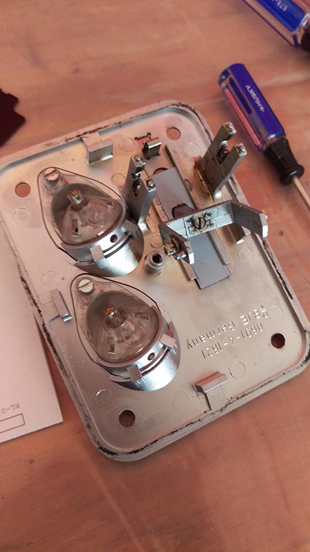
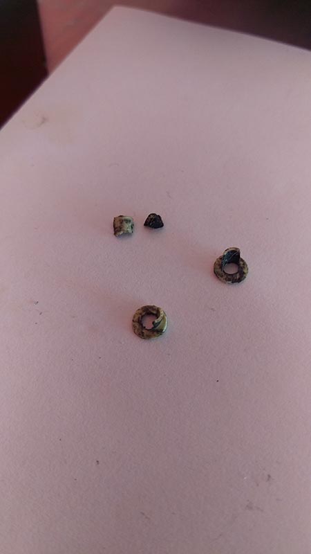
- Again, this is where you may need additional tools/steps... Unfortunately for some owners, Ferrari decided to cement the small flat-head screw into the T-handle, which means you will be unable to simply unscrew it. If yours comes out using just a screwdriver, consider yourself lucky and skip the next 2 steps.
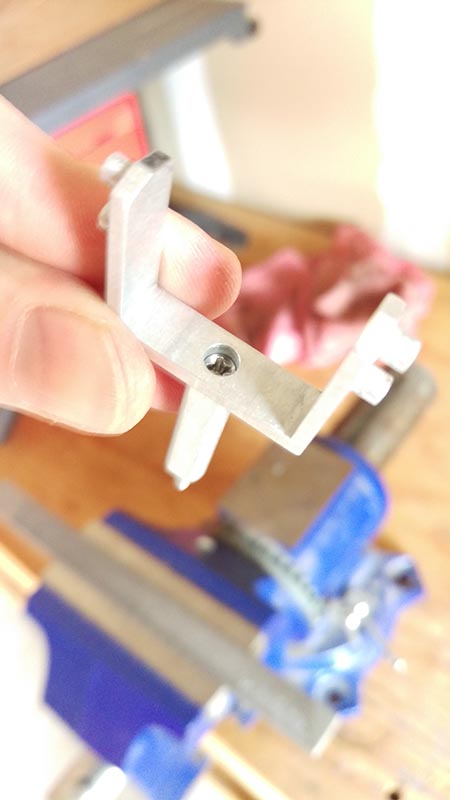
- If you are unable to remove the flat-head screw, you'll have to cut the split of the fork off. Mount the silver portion in a vice (after first wrapping the vice head in cloth to protect your parts). It may be easiest to clamp onto the T-handle and cover the exposed silver potion with more cloth to keep it from being covered in metal shavings during the cutting
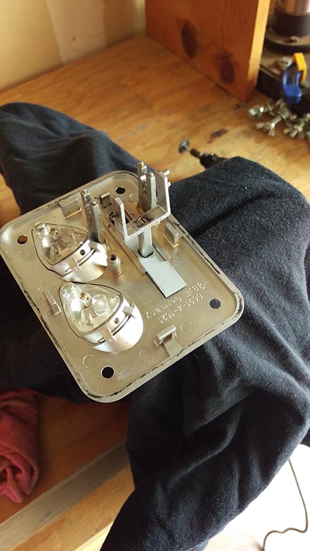
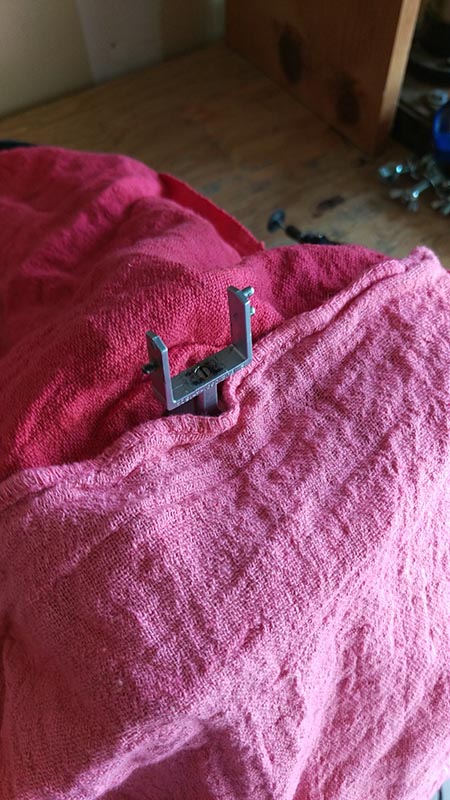
- Using a Dremel with a cutting wheel, gently cut the fork free. (You can also cut through the screw head but it is not necessary). Once the fork is removed, you can then use a pair of pliers to unscrew the cemented screw. Once the screw is free from the T-handle then you're now at the point where the lucky people found themselves. Again, you may need additional steps and tools here.
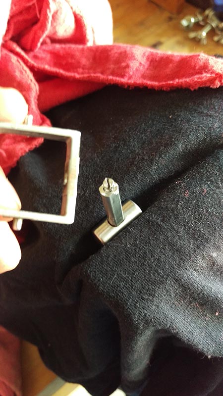
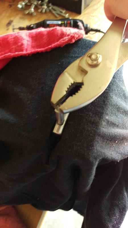
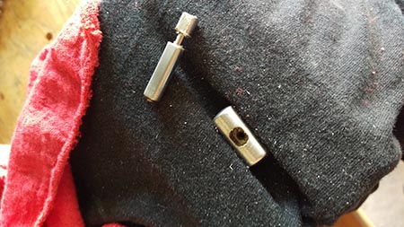
If you had to cut away the fork, you will have probably destroyed the existing flat-head screw. You will need to procure a replacement (3mm x 40mm Pan Head .5mm thread).
Another issue, once you do find the proper screw, is that the head of it will more than likely be too large and require some filing/grinding to fit. One method is to wrap the threads in tape for protection, then place the screw into a drill and grinding it against a large file held in a vice.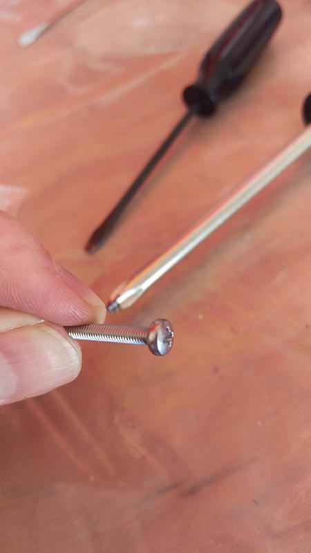
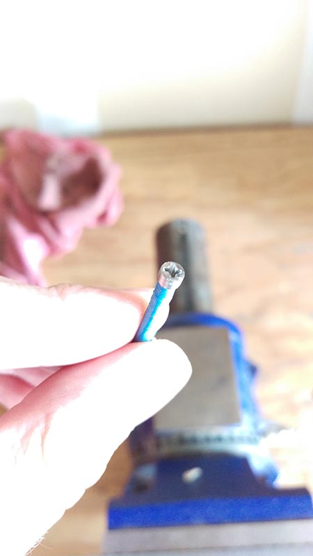
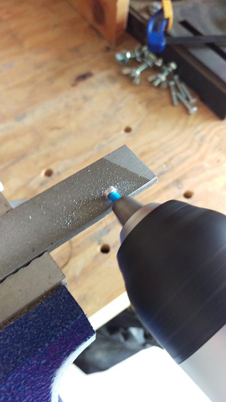
- If you had to machine a new screw, or if you were able to use your old one, just insert the new fork into the silver portion, place the T-handle on the end and insert the flat-head screw into it.
- The final step is to place the silver portion back on the black bottom and attach them with the center screw (either on the PCB, or through it, depending on whether or not you had to bore out an access hole).
One note... it is easiest to keep the fork/handle depressed while re-attaching the silver/black portions. This is to keep the springs seated in their arms. Be careful and diligent when installing the fork not to bend the springs or let them partially stick out and bend. They should be pressed down into their recesses during the re-assembly.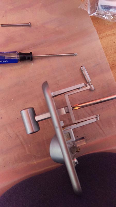
Reverse the rest of the steps to attach the black bottom plate and connect/install the unit back in the car.
You're done!
